Winding Terminologies In Dc Generator
a) Conductor : It is the actual armature conductor which is under the influence of the magnetic field, placed in the armature slot.
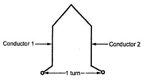
b) Turn : The two conductors placed in different slots when connected together,. forms a turn. While describing armature winding the number of turns may be specified from which, the number of conductors can be decided.
 |
| Fig. 1 Single Turn |
Z = 2 x Number of turns.
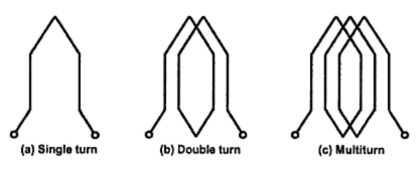
c) Coil : For simplicity of connections, the turns are grouped together to form a coil. If coil contains only one one turn it is called single turn coil while coil more than one turn is called multiturn coil.
 |
| Fig. 2 Armature coils |
Hence if number of coils, along with of number of turns per coil are specified, it is possible to determine the total number of turns and hence total number of armature conductors ‘Z’ required to calculate generated e.m.f.
Example :
A 4 pole, lap wound, d.c. generators has 42 coils with 8 turns per coils. It is driven at 1120 r.p.m. If useful flux per pole is 21 mWb, calculate the generated e.m.f. Find the speed at which it is to be driven to generate the same e.m.f. as calculate above, with wave wound armature.
Solution :
P = 4 ? = 21 mWb = 21 x 10-3 Wb N = 1120 r.p.m.
Coils = 42 and turns / coil = 8
Total turns = coils x turns / coil = 42 x 8 = 336
Z = 2 x total turns = 2 x 336 = 672
i) For lap wound, A = P

ii) For wave wound, A = 2
and E = 263.424 V
N = 560 r.p.m.