Generation Of Induced Emf And Current
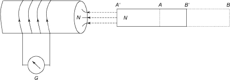
Figure 9 shows an insulated coil whose terminals are connected to a sensitive galvanometer (G). There is a bar magnet, AB, close to the coil. When the bar magnet is suddenly moved towards the coil to position A ‘B’, there is a deflection in the galvanometer. This deflection in the galvanometer lasts so long as there are relative motions of the magnet with respect to the coil; that is, the flux linking with the coil changes.
Figure 10 shows that when the magnet is withdrawn, the deflection of the galvanometer is in the direction opposite to the above case. This deflection exists so long as the bar magnet is in relative motion to the coil; that is, the flux linking with the coil changes.

Figure 9 Generation of Induced emf

Figure 10 Magnet With drawn
In both the cases, the deflection is reduced to zero when the bar magnet becomes stationary. The flux linked with the coil increases as the bar magnet approaches the coil in the first case, while in the second case, the flux linked with the coil decreases when the bar magnet is withdrawn.
It is clear from above that deflections in the two cases are in different directions. The deflection in the galvanometer indicates that there is an induced current produced in the coil. In the first case, the induced current flows through the coil in an anticlockwise direction as seen from the bar magnet. This indicates that the face of the coil is the N pole. To move the bar magnet towards the coil, a force from outside must be given to the bar magnet. When the magnet is withdrawn, the current flows in a clockwise direction, as seen from the bar magnet. This indicates that the face of the coil is the S pole. So once again force must be supplied to the bar magnet from outside to take it away from the coil. Here, the principle of conservation of energy is fully satisfied.
From the above results, Faraday proposed two laws known as Faraday’s first and second laws.
FARADAY’S LAWS
- First law: Whenever there is variation of magnetic flux linked with a coil, an emf is induced in it. Or an emf is induced in a conductor whenever it cuts the magnetic flux.
- Second law: The magnitude of this induced emf is the rate of change of flux linkage.
Let the initial flux be Φ1 and the final flux be Φ2 in time t. Let the turns of the coil be N. Therefore, the initial flux linkage is NΦ1 and the final flux linkage is NΦ2.
![]()
In differential form, we can put Equation (1) as ![]()
LENZ’S LAW
The law states that the induced current will flow in such a direction that it will oppose the cause that produces it. It is explained as follows:
The current through the coil 1 is varied by the rheostat, as shown in Figure 11. An emf is induced in coil 2 due to variation of flux in coil 1. The induced emf between P and Q will be such that the current will flow from P to Q via the resistance R so that it will oppose the flux that is linked with it. In this case Pwill have a positive polarity and Q will have a negative polarity. The induced emf is given by .

Figure 11 Example of Lenz’s Law